Are you planning to construct a healthcare facility? Perhaps a hotel, which will require totally different drawings? Regardless of what kind of construction project you’re overseeing, mechanical drawings(part of the construction drawings) will be one of the most important things to get right.
Table of Contents:
Introduction
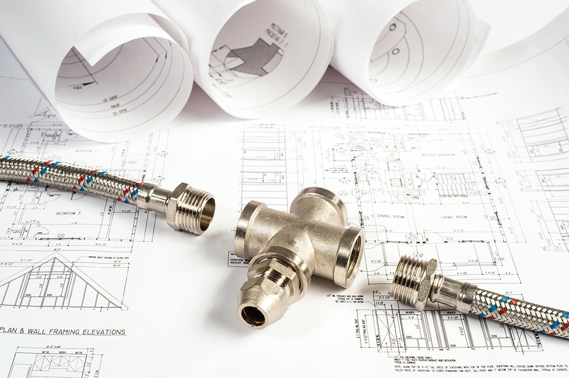
A mechanical drawing is a technical drawing that displays information about various mechanical systems, such as HVAC (heating, ventilation, and air conditioning). Mechanical drawings are often combined with electrical and plumbing drawings to create MEP drawings.
The job of mechanical drawings is to accurately identify all geometric features of the machine component. To convey all product information to the manufacturer, it includes various orthographic views, which are also sometimes called orthogonal projections or multiview drawings. Orthographic projections represent 3D objects, viewed from a perpendicular position to the drawing plane.
Mechanical engineering drawings are relevant because they help communicate issues and solutions and define what needs to be done. Once they are complete, they are considered part of the construction drawings, which are further utilized to apply for building permits. Furthermore, they can be used to help determine the price of a project.
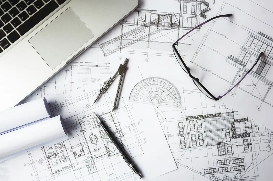
Traditionally, mechanical drawings are made by hand, with the aid of drafting instruments such as compasses. Sheets of paper are placed on drafting tables, which are slanted toward the draftsman.
Recommended Reading:
Mechanical vs Engineering Drawing
Many times, the terms “mechanical drawing” and “engineering drawing” are used interchangeably.
However, note that engineers often call mechanical drawings “blueprints.” This may not necessarily be accurate (or, rather, literal) in today’s age since the term refers to the blue carbon papers used for drawings before they were replaced by technologies such as CAD.
Types of Mechanical Drawings
In terms of the way mechanical drawings are developed, there are two types:
- Manual Drawings
- Computer-aided Design (CAD) Drawings
Manual Drawings
Manual drawings are made by hand, using instruments such as protractors, rulers, pencils, and sheets. Unfortunately, due to drawing errors and ambiguity, manual drawings can be easily misread.
Computer-aided Design (CAD) Drawings
CAD drawings have become the standard of the day. They can be divided into 2D and 3D CAD. Sometimes, 3D CAD is a part of a process called Building Information Modeling (BIM), which is increasingly required by law in various locations.
2D CAD
2D CAD is often done in AutoCAD. With AutoCAD, you can develop curves and straight lines. The software also makes it easier to rectify mistakes.
3D CAD
3D CAD systems include Autodesk Revit, SolidWorks, and Rhino 3D. AutoCAD is also used, as it is a versatile and reliable tool. These systems render both mechanical parts and larger mechanical systems. The software provides section views, orthographic projections, and projected views.
Recommended Reading:
Pictorial vs Orthographic Drawings
There are two common styles of mechanical drawing: pictorial and orthographic.
In pictorial or 3D drawings, the drawing looks like (you guessed it) a 3D object. Pictorial styles include perspective, isometric and oblique drawings, with isometric drawings being the most common. While pictorial drawings make it easy to imagine what the object will look like, they can skew the object dimensions.
On the other hand, orthographic projections use one drawing to display various views of the object from different directions. The viewing directions are at right angles and might include an elevation, front view, top view and an end view.
What Do Mechanical Drawings Include?
Before we start on our list, note that some consultants may prefer the HVAC drawings to be prefixed by “H,” the plumbing drawings to be prefixed by “P,” and the fire protection drawings to be prefixed by “FP.”
The majority of the work displayed on these drawings is in plan view. Due to the fact that mechanical drawings are diagrammatic in nature, the plan view provides the most useful illustration of the configuration and location.
With that, let’s get into what mechanical drawings include:
- The cover sheet will contain the legends (table/chart of abbreviations or symbols), appropriate notes, and details
- Title blocks. These include additional data, such as: the designer’s name, finish, material, part number & description, general tolerances, units, scale, and part weight
- If a part is an assembly, you should also include a bill of materials. This will list the quantities and items needed
- Manufacturers can ensure they’re using the most recent version through a revision block
- Break lines, which show where a view is broken. These are useful to show information without cluttering up space.
- Continuous lines, which represent the physical boundaries of an object
- Center lines, which show the geometric center of an assembly. They can indicate slots, holes, and other features that have symmetric properties without overcrowding the drawing
- Hidden lines, which show spaces that would not otherwise be visible in a certain view, such as edges behind a face
- Mechanical plans are identified as M-1, M-2, M-3, and so on. These specify the following: design and any modifications of mechanical system, ductwork dimensions & layout, damper locations, design air-delivery rates, thermostat locations, diffuser locations, and if needed, any supplemental cooling systems.
- Additional information is shown in the section, and auxiliary or detailed views can be helpful, but they are not necessary for specific designs. Hence, you should only include views that are crucial to understanding a part. Isometric views are beneficial but not required.
- Tolerances that are necessary to producing parts.
- Tuning vanes
- Thermostats
- HVAC units
- Dampers, heat registers, return air grilles
- Exhaust fans
- Smoke detectors
- Firestat re-ducting
- Heat loss and gain calculations
- Water, electrical, and gas connections
- Inspection & quality requirements so that the manufacturer knows what to search for and how to inspect the parts. This way, the manufacturer can meet your expectations
- Mention both your preferred and alternative materials. This will give the manufacturer some flexibility and help make sure your costs remain low. For example, you could consider optional coatings, post-processing methods, or markings
Note that, for additively manufactured or injection molded parts, you should avoid over-dimensioning. This is because your manufacturer might have difficulty identifying the dimensions that are the most important.
You should also exclude tolerances that are unnecessarily tight, since these may raise costs without improving function.
These drawings are a crucial part of any construction plan. We hope this article has given you a good starting point for understanding them.
Note that mechanical engineering drawings can be time-consuming and complex to create. That’s why BluEntCAD can take care of them for you. We provide accurate drafting services to home builders, real estate developers, large architectural and engineering companies, and custom home designers. Browse our portfolio to see how we’ve helped businesses like yours!
Ready to make your next project a success with construction drawings? Contact us now!





 Must-Ask Questions Before Outsourcing CAD Drafting Services
  How BluEnt Ensures Construction Documentation is Accurate and Up-to-Date?
  Why CAD Drawings Are Crucial for Sustaining the Modern Architecture Industry?
  How is Artificial Intelligence in Construction Design Transforming Architectural Landscape?