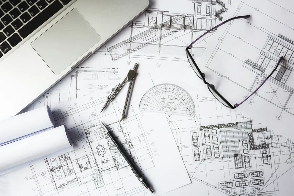
Unlike artistic drawings, which can be interpreted in many ways, technical construction drawings convey only one specific meaning. They are created to visualize architectural and engineering projects and showcase the functions and features of the structures. Most drawings that are created during the construction and design stages can be considered technical drawings.
Table of Contents:
What are Technical Drawings?
A technical drawing (also called an engineering drawing), in this article’s context, is one of the types of drawings used for building design and construction. It has a broad meaning and refers to any drawing that conveys the way a structure functions or how it is built.
Technical drawing is often the main form of communication between the designer and the client. These drawings are used by all stakeholders in the project, including architects, plumbers, engineers, contractors, and electricians for developing modular components.
- Technical construction drawings give you a clear idea of the modules, structures, and components included.
- You can easily and quickly modify, edit, or transform the drawings.
- The technical drawing basics are typically finished during the design development phase. They become more specific and detailed as the project goes on.
Which Documents are Considered Technical Construction Drawings?
- Shop drawings
- Detail drawings
- Assembly drawings
- Design intent drawings
- Installation drawings
- Working construction drawings
- Component drawings
- As-built drawings
- General arrangement drawings
- Record drawings
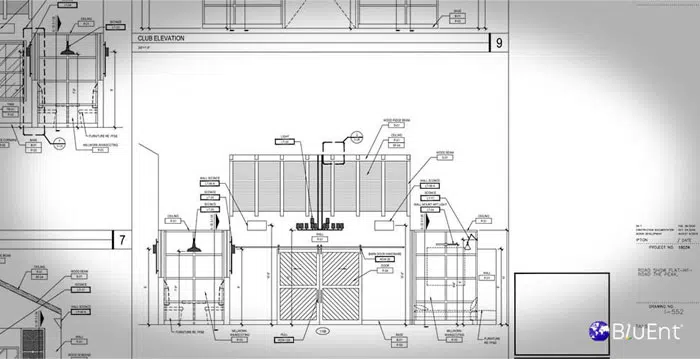
Common Components of Technical Construction Drawings
- Title block: Appears in the bottom right corner of the drawing and conveys information relating to the company that prepared the drawing, revisions, scale, etc.
- Revision block: Appears in the top right corner and conveys the revision number, specific changes, approval, etc.
- Views & projections: Top, side and front views of the structure.
- Scale: Often provided in the title block.
- Basic symbols: Identifies features such as doors, windows, brickwork, and topography.
- Border: Most technical drawings have a border, which might include numbers and letters for zones.
- Circled numbers: Used when the scale is too small and indicates that the section is shown in greater detail on a different page.
- Notation & units: Consistent notation conventions should be followed for clear communication.
- Abbreviations: Used to indicate instructions and elements. Eg., DR = door, BSMT = basement.
How to Create a Technical Construction Document
Technical drawings may consist of orthogonal (2D) plans, elevations, and sections or exploded projections (3D).
These can be drawn to scale manually or rendered using Computer Aided Design (CAD). The latest practice is to create 3D models of structures and components through Building Information Modeling (BIM) software. The drawings’ purpose should always be considered, so that they are adequately structured.
- Graphical techniques, like hatching and varying line thickness, can give further clarity.
- For conveyance of precise information, the drawings can include notations, dimensions, symbols and title blocks. These should be consistent with industry standards.
- The drawings’ scale should always reflect the information required.
Types of Technical Construction Drawings
There are two basic ways of creating technical drawings: hand drawing and rendering.
Hand Drawn Technical Drawings
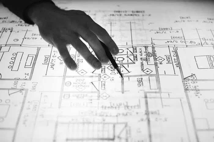
These drawings, as the term suggests, are created manually. Various aspects of a component such as dimensions, isometric drawing and orthographic drawing can be represented with the right hand drawn technical drawings.
Hand drawn technical drawings should not be confused with sketches. Technical drawings use drawing instruments and require accuracy and precision while sketching is more freehand and easier to edit.
While many professionals believe that sketches can coexist with rendering, since sketches are good for bouncing ideas off clients and investors, it generally appears that computers have won over technical drawings.
Renderings

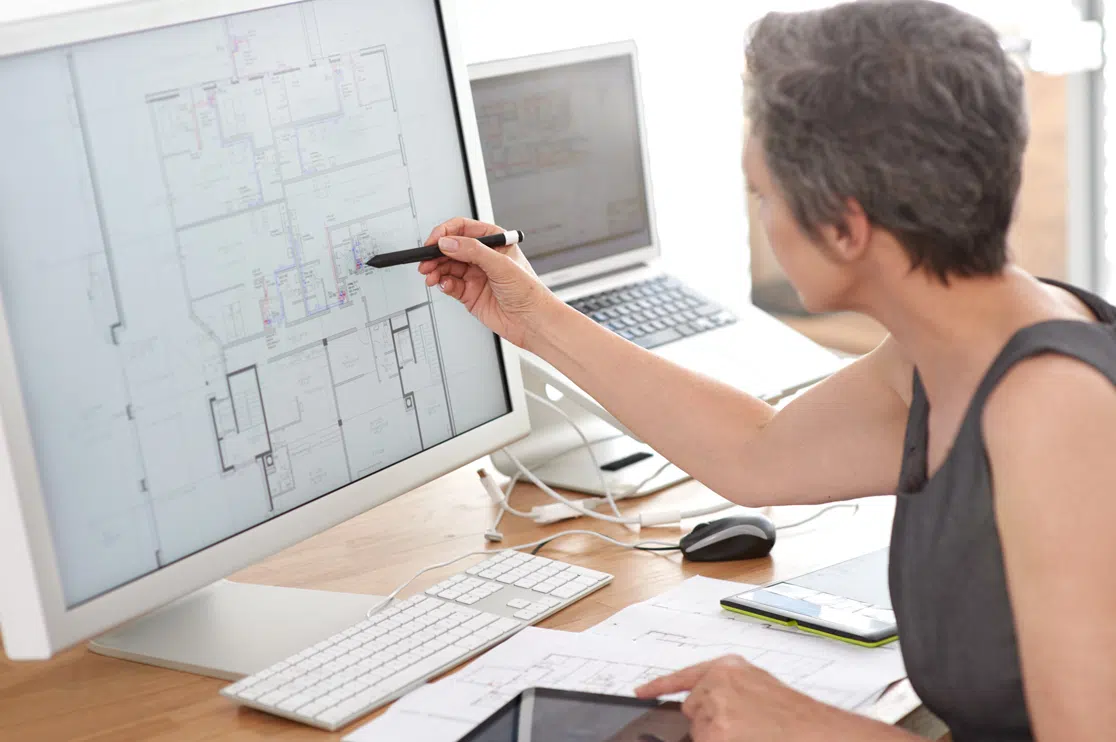
Renderings are made with CAD, of which two systems are 2D and 3D.
2D systems such as AutoCAD replace paper drawings. They can be used to develop plans for large projects, such as aircraft and buildings. However, they do not provide a way to verify how the many components will fit together.
One of the greatest strengths (or perhaps the greatest one) of 2D CAD systems is their time-saving capacity. In manual drawings, if a single mistake is found or a change is required, you need to create a new drawing from scratch. However, in a 2D system, a copy of the original can be changed.
3D CAD systems such as SolidWorks work like this:
- The geometry of the part is produced.
- User-defined views of the geometry help create the technical drawing.
- Any sectioned, orthographic or projected view is developed by the software.
With rendering, 2D images can be easily converted to 3D life-like drawings. Furthermore, elements such as shadows, color, and lamination can be introduced to create more realistic images. This helps in both marketing and construction.
Hand Drawings vs Rendering
Hand drawings and renderings are both important for the design process. Hand-drawn designs breathe life into the initial project conceptualization.
By translating an idea into a 2D design, the doors to communication are opened between the client and the designer. These designs can be changed to include modifications. Once a 2D design is finalized, it can be translated into a photorealistic 3D model with rendering.
Best Practices
For the most reliable technical drawings, the following practices should be observed:
- The scale of the drawings must reflect the detailing that is to be conveyed.
- While making the drawings, follow best practices for annotation and documentation. This will make them easy to read and allow for quick conversion to renders.
- Keep specification information separate to avoid contradiction and duplication.
- Remember the supplier and part number on the drawing wherever hardware installation is needed.
The best way to get the right technical drawings is to hire an experienced design and drafting company such as BluEntCAD. We provide technical construction drawing services to homebuilders, architects, real estate developers, engineering companies, and home designers for large—to medium-sized projects.
Browse our portfolio to see how we’ve helped companies like yours.
Ready to make your project a success with technical drawing services? Contact us now!
Maximum Value. Achieved.





 Must-Ask Questions Before Outsourcing CAD Drafting Services
  How BluEnt Ensures Construction Documentation is Accurate and Up-to-Date?
  Why CAD Drawings Are Crucial for Sustaining the Modern Architecture Industry?
  How is Artificial Intelligence in Construction Design Transforming Architectural Landscape?