Black sail ship on body of water.
If you’re in the construction, architecture, or steel fabrication industry, you’ll know about structural fabrication drawings. But why is it crucial to get them exactly right?
Table of Contents:
Introduction
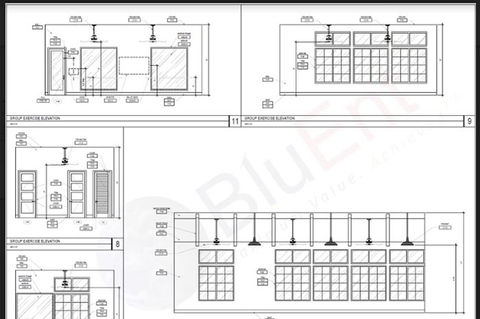
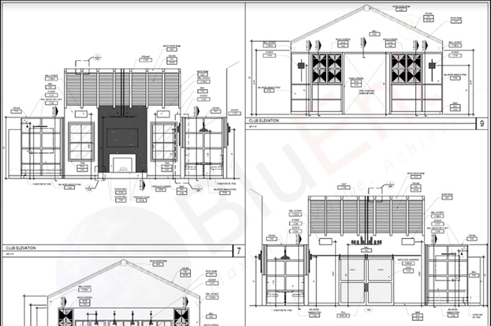
A fabrication drawing is developed by the fabricator, contractor, manufacturer, or supplier. It provides sections and views including bolting and welding information, dimensions, details and standards. That is, it includes details on how various structural elements are designed, manufactured, assembled and installed.
Structural metal shop drawings are used for:
- Beams, stairs, bracing, columns, ladders, handrails, trusses and frames, and so on.
- Embed layout plans and anchor setting plans.
- Steel erection drawings, both main and miscellaneous.
- Data files that show all pre-fabricated components.
This information simplifies the fabrication process. Detailed metal shop drawings will help in attaining architectural approvals and can increase the profitability of your project.
A good fabrication drawing will guide the contractor with up-to-date details. However, a great fabrication drawing will arm your on-site contractor with accurate measurements and the total number of elements required for completing the project.
Unlike design drawings, which are aesthetic renderings or concepts, shop drawings translate the design intent with detailed drawings. Furthermore, compared to construction documents, shop drawings contain more details.
Recommended Reading:
Your shop drawings should contain the following:
- Comparison information for the engineer and architect.
- Suggestions of where verification of jobsite dimensions is required.
- Alterations or changes from the construction documents.

Of course, it goes without saying that inaccurate structural fabrication drawings will delay schedules and cause damage on-site.
Fabrication Drawings 101: Types of Fabrication Drawings
When you work with an expert fabrication design team, you can expect to receive three basic fabrication drawings.
These play an instrumental role in complex construction projects. Furthermore, all of these drawings require several drawings in sundry views.
Let’s look at the types of fabrication drawings.
-
Metal Fabrication Drawings
These illustrate the various metal components that are going to be used in your building, with details on manufacture, supply, assembly and installation.
They comprise of fabrication shop drawings and sheet metal drawings.
-
Single Part Drawings
Single part drawings are workshop drawings that display fabrication information for a single part, typically sans welds. Generally, they use smaller sheet sizes, such as A4.
These drawings focus on the more complex details of your construction project. These comprise of specific details for cutting materials, dimensions, and the weight of individual components.
-
Assembly Drawings
When individual components are ready, they are sent to the welder to assemble, accompanied by assembly drawings. These drawings include information on the bill of materials and finishes.
Assembly drawings contain fabrication information for a single assembly. Generally, an assembly will consist of a main part and various secondary parts, which are bolted or welded to a main part. Sheet sizes are larger than those of single part drawings, such as A3.
-
General Arrangement Drawings
General arrangement drawings, or GA drawings, are master plans, and talk about how all components fit together to create one unit.
They are contract documents containing information pertaining to general arrangement structural elements. A GA drawing shows the overall composition of an object, such as a building, and is typically created with Computer-Aided Design (CAD) or in the BIM workflow.
Consulting structural engineers commonly use GA drawings to convey a structure to public authorities and to legal, construction, design and costing teams. GA drawings display models from various directions. Furthermore, they often include enlarged views of more complex details or areas.
General arrangement drawings may also be called “location drawings”, because they show the locations of various assemblies and components. However, these might be confused for drawings that indicate the geographical location of a building.
What Do Great Structural Fabrication Drawings Do?
Incorrect fabrication drawings will cost you money, resources and time. Furthermore, they will causing damage to erected structures and jeopardize the safety of workers and residents.
However, great fabrication drawings will give you long-lasting, safe structures.
-
Your Building’s Metal Structures Will Be Assembled Correctly
Incomplete information in drawings might lead the on-site contractor to assemble structures incorrectly. The structures will no longer have the same safe specifications. Furthermore, they will take up more time and effort to assemble.
Recommended Reading:
-
Meet Fabrication Drawing Standards
Most AEC industry veterans know the stringent standards tests and quality assurance checks that the fabrication drawings undergo.
Not performing the QA tests and rushing into construction is only going to cause further delays and wastage.
-
Prevent Getting Stuck in the Middle of Construction
Sub-par fabrication drawings mean you are not going to order the materials you actually require.
And getting stuck in the middle of construction due to lack of materials or incorrect supply is only going to cripple your schedule.
-
Safety First!
Incorrectly installed components, the wrong materials, and missed deadlines will compromise the safety of both workers and residents.
Recommended Reading:
How to Ensure That You Have the Right Set of Fabrication Drawings
Before you send your structural fabrication drawings to a construction site, make sure that the drawings pass the review process.
- Pay attention to details. What goes where and how much of what is required is crucial to creating reliable fabrication drawing sets.
- An on-site visit to the construction site is often required for gauging the full scope of what you are planning to put on paper.
- Get your drawings reviewed by in-house supervising managers, stakeholders and other relevant parties who have a say in construction.
Conclusion
We hope this article has given you an insight into why detailed and accurate fabrication shop drawings are necessary for a successful construction project.
Unfortunately, due to budget cuts and mounting pressure on engineers, the quality of design deliverables can drop. That’s why it’s crucial to have a team of experts who can accurately translate design drawings into shop drawings.
Such a team exists at BluEntCAD. We’ve been operating in the AEC industry since 2003 and are thoroughly familiar with the fabrication process. Having already served most of the US’ major homebuilders, we bring a level of experience that translates to ease and efficiency for you and your business.
We serve:
- Railing manufacturers and installers, curtain wall manufacturers, ceiling manufacturers, signage manufacturers and installers
- Concrete subcontractors, metal contractors, design build contractors
- Large architectural and engineering companies, real estate developers, large homebuilders
Ready to take your business to the next level with the support of a great shop drawing company? Contact us now!
Maximum Value. Achieved.




 Shop Drawings Vs Fabrication Drawings? Easy Explanation with Example
  What are Types of Fabrication Drawings, and Why Are They Necessary for Your Project?
  What’s the Difference Between Shop Drawings vs Construction Drawings vs As-Built Drawings
  AutoCAD And RFMS: Find the Perfect Fit for Your Tile & Stone Shop Drawing Projects
Hey,
Great content! Got to know the importance of detailed and accurate fabrication shop drawings for a successful construction project. Keep posting!
Thanks
I read this article this is really very informative and different from another article and your content language is very easy and comfortable for understanding the topic. really this is very helpful.
Thanks a lot! for this article.
It really interests me to read such articles, thanks for sharing. Blogs like yours really helps me learn more day by day.
Thank you, Emily! We’re glad they help. Do let us know if you would like us to cover any other topics.
thanks for your sharing!
Thank you! And you are very welcome. If you would like us to cover any other topic, please reach out to us at cad@bluentcad.com